
Hyundai Santa Fe (TM): Air conditioning System / Compressor. Components and components location
| Components |
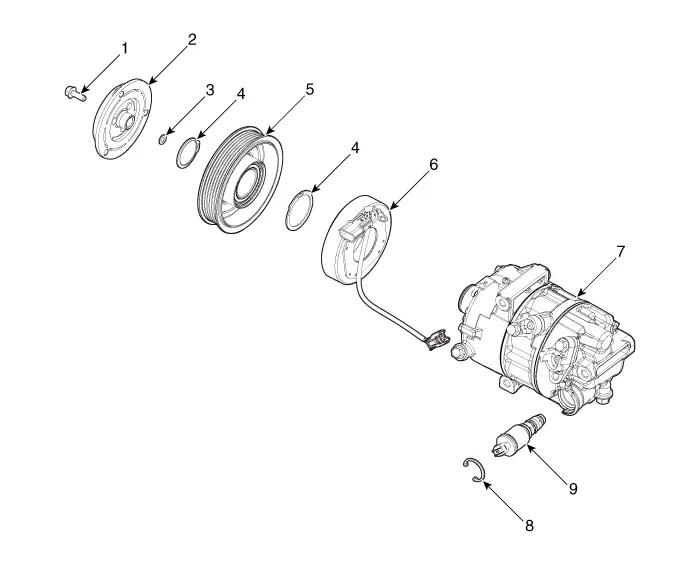
| 1. Clutch Bolt 2. Disc & Hub Assembly 3. Clutch Spacer 4. Snap Ring 5. Pulley |
6. Magnetic Coil
Assembly 7. Compressor 8. Electric Control Valve (ECV) spacer 9. Electric Control Valve (ECV) |
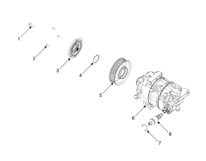
| 1. Clutch Bolt 2. Limiter Bolt 3. Limiter & Damper Assembly 4. Snap Ring |
5. Pulley 6. Compressor 7. Electric Control Valve (ECV) spacer 8. Electric Control Valve (ECV) |
Description The compressor is the power unit of the A/C system. It is located on the side of engine block and driven by a V-belt of the engine.
Removal 1. If a compressor is available, the air conditioner is operated for a few minutes in the engine idle state and then the engine is stopped.
Other information:
Hyundai Santa Fe (TM) 2019-2023 Service and Repair Manual: Seat Electrical
Components and components location Component Location 1. Lumber support motor (Vertical) 2. Lumbar support motor (Horizontal) 3. Reclining motor 4. Rear height motor 5. Front height motor 6. Slide motor 7.
Hyundai Santa Fe (TM) 2019-2023 Service and Repair Manual: Front Radar Unit. Repair procedures
Inspection Inspection procedure for vehicle with Forward Collision-Avoidance Assist and Smart Cruise Control system failure 1. Check the bumper appearance for accident (check the vehicle appearance visually and see bumper replacement history).
Categories
- Manuals Home
- Hyundai Santa Fe Owners Manual
- Hyundai Santa Fe Service Manual
- Vehicle Information, Consumer Information and Reporting Safety Defects
- Lane Following Assist (LFA)
- Rear Disc Brake. Repair procedures
- New on site
- Most important about car
