Hyundai Santa Fe (TM): Body (Interior and Exterior) / Floor Console
Components and components location
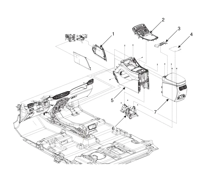
1. Floor console
side cover
2. Floor console upper cover
3. Console armrest lock assembly
4. Storage box mat
|
5. Front floor
console assembly
6. Rear console mounting bracket assembly
7. Rear floor console assembly
|
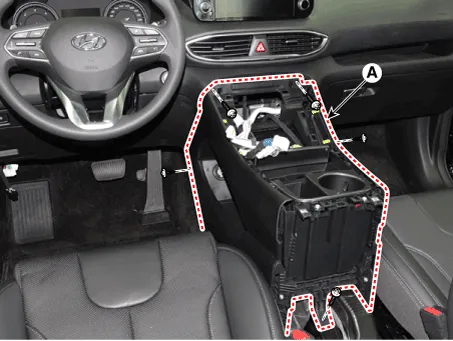
Floor Console Assembly. Components and components location
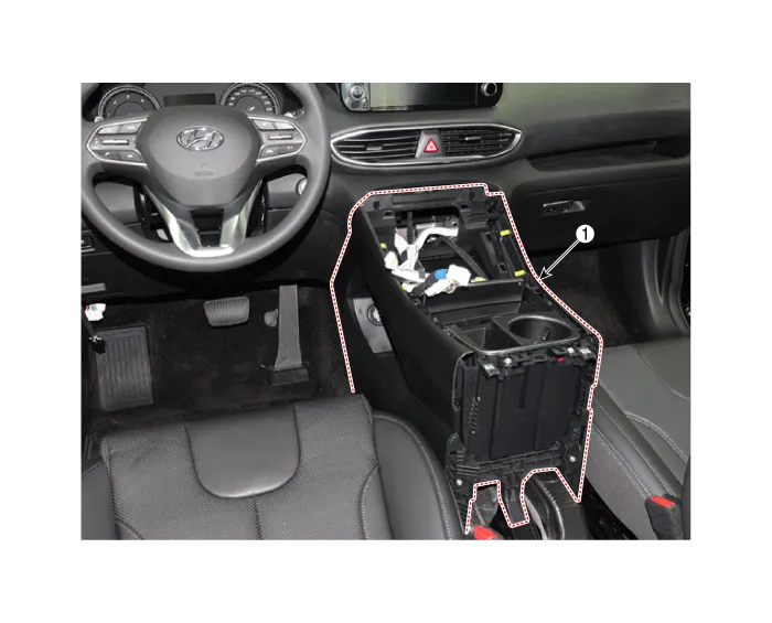
1. Front Console
Assembly
|
|

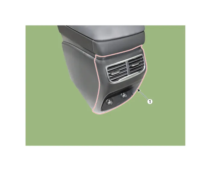
1. Rear Floor
Console Assembly
|
|
Floor Console Assembly. Repair procedures
[Rear Floor Console Assembly]
| •
|
When removing with a flat-tip screwdriver or remover, wrap protective
tape around the tools to prevent damage to components.
|
| •
|
Put on gloves to prevent hand injuries.
|
|
| •
|
Take care not to bend or scratch the trim and panels.
|
|
|
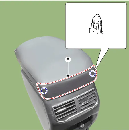
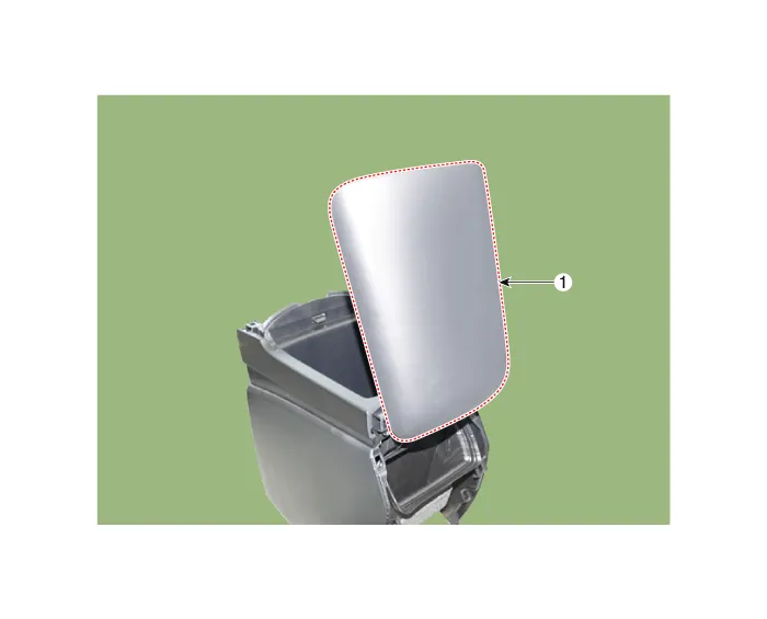
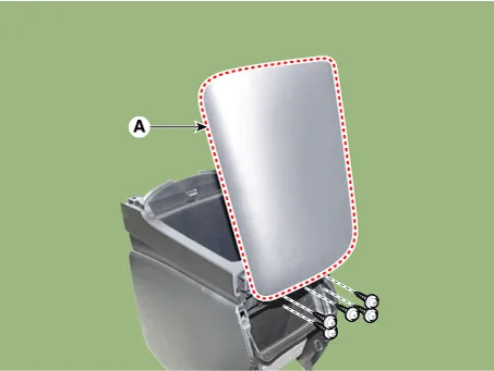
1. |
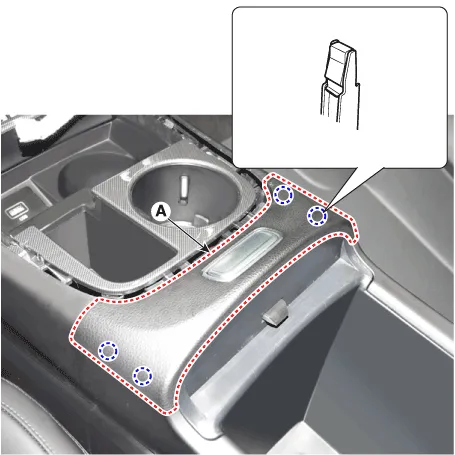
Remove the console upper cover (A).
|
|
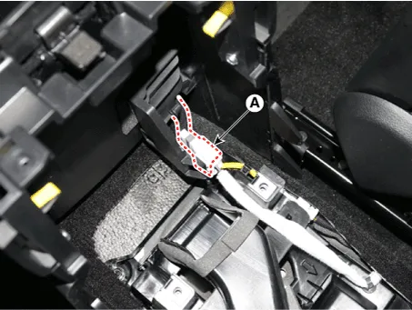
2. |
Press the lock pin, separate the connectors (A).
|
|
3. |
Remove the console armrest lock assembly (A).
|
|
4. |
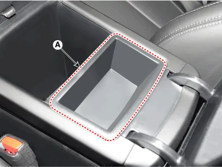
Remove the console armrest tray (A).
|
|
5. |
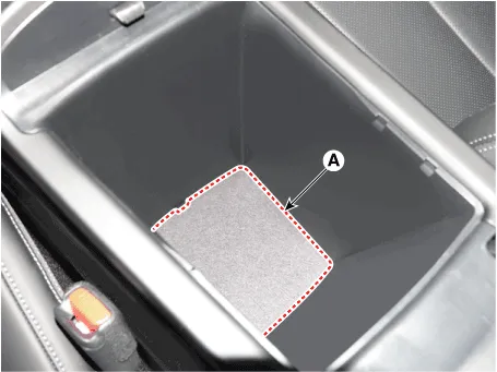
Remove the storage box mat (A).
|
|
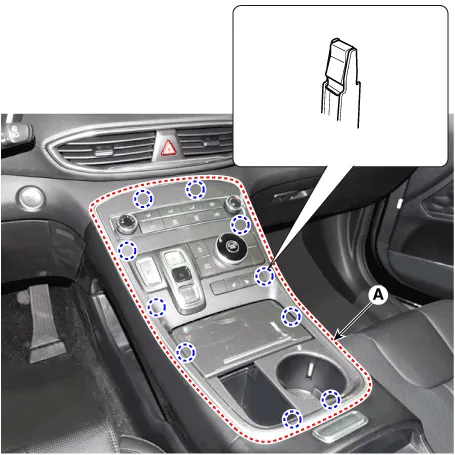
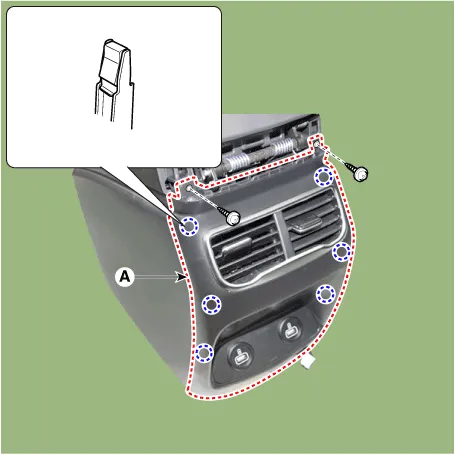
6. |
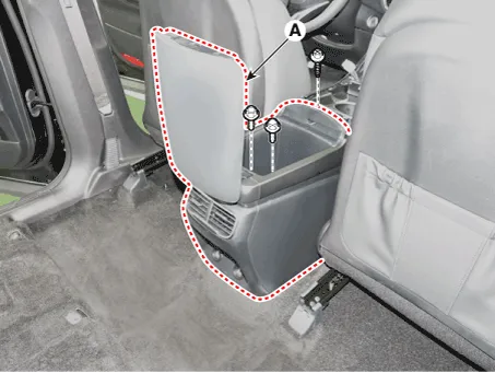
Loosen the mounting bolts and screw, remove the rear floor console assembly
(A).
|
|
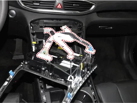
7. |
Press the lock pin, separate the connector (A).
|
|
8. |
To install, reverse removal procedure.
|
• |
Make sure the connector is connected properly.
|
|
• |
Replace any damaged clips (or pin-type retainers).
|
|
|
[Front Floor Console Assembly]
| •
|
When removing with a flat-tip screwdriver or remover, wrap protective
tape around the tools to prevent damage to components.
|
| •
|
Put on gloves to prevent hand injuries.
|
|
| •
|
Take care not to bend or scratch the trim and panels.
|
|
|
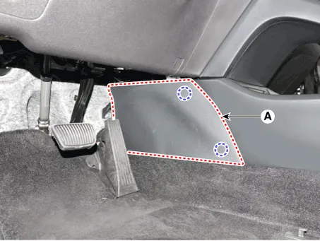
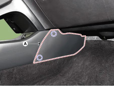
1. |
Remove the console side cover (A).
[LH]
[RH]
|
|
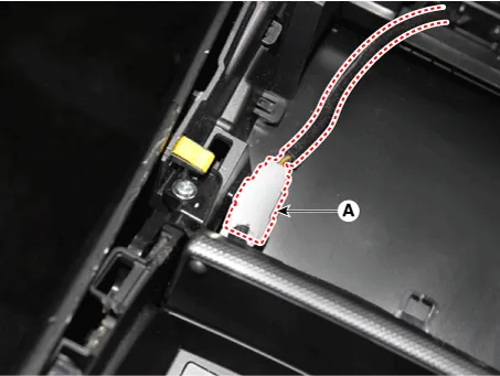
2. |
Press the lock pin, separate the connector (A).
|
|
3. |
Loosen the mounting screws, remove the front floor console assembly
(A).
|
|
4. |
Press the lock pin, separate the connectors (A).

|
|
5. |
To install, reverse removal procedure.
|
• |
Make sure the connector is connected properly.
|
|
• |
Replace any damaged clips (or pin-type retainers).
|
|
|
Rear Console Cover. Components and components location
Rear Console Cover. Repair procedures
| •
|
Put on gloves to prevent hand injuries.
|
|
| •
|
When removing with a flat-tip screwdriver or remover, wrap protective
tape around the tools to prevent damage to components.
|
| •
|
Use a plastic panel removal tool to remove interior trim pieces
without marring the surface.
|
| •
|
Take care not to bend or scratch the trim and panels.
|
|
|
1. |
Remove the rear console assembly.
(Refer to Floor Console - "Floor Console Assembly")
|
|
2. |
Remove the rear console upper cover (A).
|
|
3. |
Press the lock pin, separate the connectors (A) and then loosen the
mounting screws (B).

|
|
4. |
Loosen the mounting screws, remove the rear console cover (A).
|
|
5. |
To install, reverse removal procedure.
|
• |
Make sure the connector is connected properly.
|
|
• |
Replace any damaged clips (or pin-type retainers).
|
|
|
Console Armrest. Components and components location
Console Armrest. Repair procedures
| •
|
Put on gloves to prevent hand injuries.
|
|
| •
|
When removing with a flat-tip screwdriver or remover, wrap protective
tape around the tools to prevent damage to components.
|
| •
|
Use a plastic panel removal tool to remove interior trim pieces
without marring the surface.
|
| •
|
Take care not to bend or scratch the trim and panels.
|
|
|
1. |
Remove the rear console assembly.
(Refer to Floor Console - "Floor Console Assembly")
|
|
2. |
Remove the rear console cover.
(Refer to Floor Console - "Rear Console Cover")
|
|
3. |
Loosen the mounting screws, remove the console armrest (A).
|
|
4. |
To install, reverse removal procedure.
|
• |
Replace any damaged clips (or pin-type retainers).
|
|
|
Components and components location
Component Location
1. Cowl Top Cover
Repair procedures
Replacement
1.
Components and components location
Components (1)
1. Crash pad
lower panel
2. Crash pad assembly
3. Crash pad
side cover [LH]
4.
Other information:
Troubleshooting
Problem Symptoms Table
Before replacing or repairing air conditioning components, first determine if
the malfunction is due to the refrigerant charge, air flow or compressor.
Use the table below to help you find the cause of the problem.
Heater & A/C Control Unit (Manual). Components and components location
Component
Connector Pin Function
Pin No
Connector A
Connector B
1
Battery
Low
2
ISG B+
Common
3


