Hyundai Santa Fe (TM): Body (Interior and Exterior) / Rear Bumper
Components and components location
| Components |
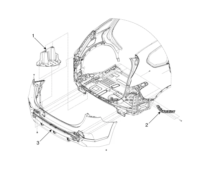
| 1. Rear Bumper
Side Under Cover 2. Rear Bumper Side Bracket |
3. Rear Bumper
Assembly |
Rear Bumper Assembly. Components and components location
| Component Location |
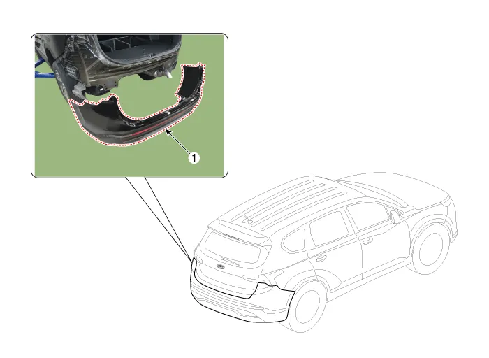
| 1. Rear Bumper
Assembly |
Rear Bumper Assembly. Repair procedures
| Replacement |
|

|

| 1. |
Remove the plug hole, loosen the mounting screws and then remove the
rear combination lamp (A).
|

| 2. |
Press the lock pin, separate the rear combination lamp connector (A).
|

| 3. |
Loosen the rear bumper mounting clips.
[Upper]
[Lower]
|


| 4. |
Loosen the mounting nut and clips, remove the urea tank cover (A).
|

| 5. |
Loosen the mounting nuts, disengage the urea tank (A).
|


| 6. |
Loosen the rear bumper assembly mounting bolts (A).
[LH]
[RH]
|


| 7. |
Press the lock pin, separate the rear bumper main connector (A).
|

| 8. |
Loosen the mounting screws and retainer on the side of rear bumper (A),
detach the side part of rear bumper.
|

| 9. |
Remove the rear bumper assembly (A).
|

| 10. |
To install, reverse removal procedure.
|

Rear Bumper beam Assembly. Components and components location
| Component Location |
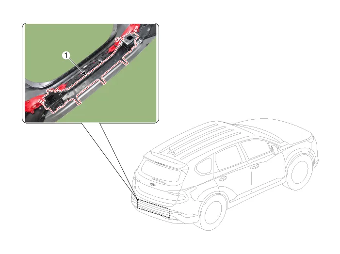
| 1. Rear Bumper
Beam Assembly |
Rear Bumper beam Assembly. Repair procedures
| Replacement |
|
|
| 1. |
Remove the rear bumper assembly.
(Refer to Rear Bumper - "Rear Bumper Assembly")
|
| 2. |
After loosening the mounting clips, remove the rear bumper beam assembly
(A).
|

| 3. |
To install, reverse removal procedure.
|
Components and components location Components 1. Front bumper side bracket [LH] 2. Front bumper side bracket [RH] 3.
Front Seat Assembly. Components and components location Component Location 1. Front seat headrest 2. Front seat back cover 3.
Other information:
Hyundai Santa Fe (TM) 2019-2023 Service and Repair Manual: Heater
Heater Unit. Components and components location Component Location 1. Heater Unit Assembly Components 1. Heater unit assembly 2. Heater NVH pad 3. Heater seal duct 4.
Hyundai Santa Fe (TM) 2019-2023 Service and Repair Manual: Front View Camera System
Description and operation Description and Operation Blcok Diagram • This system monitors the driving situations through the radar and the camera.
Categories
- Manuals Home
- Hyundai Santa Fe Owners Manual
- Hyundai Santa Fe Service Manual
- Engine Mechanical System
- Battery. Specifications
- Blower
- New on site
- Most important about car
