Hyundai Santa Fe: Surround View Monitor (SVM) / Repair procedures
| Inspection |
Tolerance Compensation
Tolerance compensation compensates for the error margins of surround view video
that occur due to the installation tolerance when the four cameras that comprise
the SVM system are installed.
You must carry out tolerance compensation if you do any of the following.
| – |
Remove and install a wide camera.
|
| – |
Conduct a body task that causes the focus of the wide camera to change,
such as a trunk task.
|
| – |
Replace the door mirror that has a wide camera.
|
| – |
Replace the SVM Controller.
|
Tolerance Compensation Environments
There are two types of tolerance compensation [manual tolerance compenstation]
and [automatic tolerance compensation].
The service center with the SVM exclusive workshop performs [automatic
tolerance compensation].
The maintenance environment lacking an SVM exclusive workshop performs
[manual tolerance compensation].
|
The Procedure of Manual Tolerance Compensation
| 1. |
Advanced preparations will be made according to the following.
|
| 2. |
The following processes will be performed to confirm whether or not
the SVM ECU and camera are working properly before engaging tolerance
compensation mode.
|
| 3. |
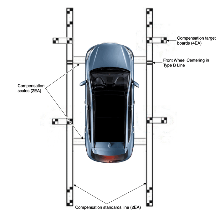
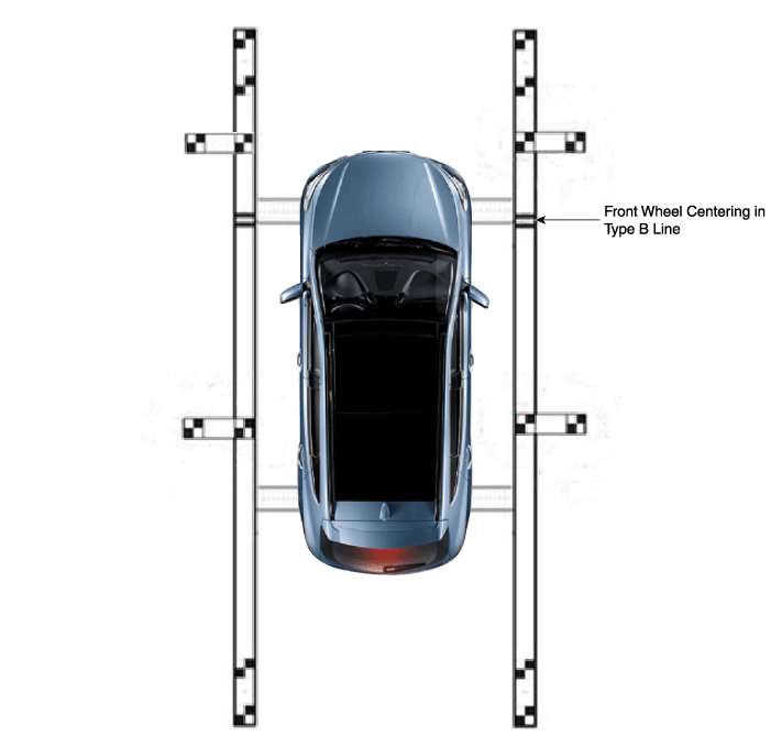
Install around the vehicle by referring to the guide that was provided
along with the compensation scales (2), compensation standard line boards
(2), and compensation target boards (4).
|
| 4. |
Keep the IG on while the car is stopped, confirm the location of the
gear stick is on ‘N’ and engage the parking brake on a flat area.
|
| 5. |
Perform the work with the parking/view switch in the vehicle set to
‘ON.’
|
| 6. |
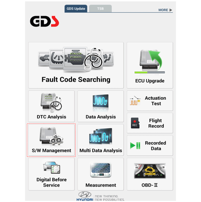
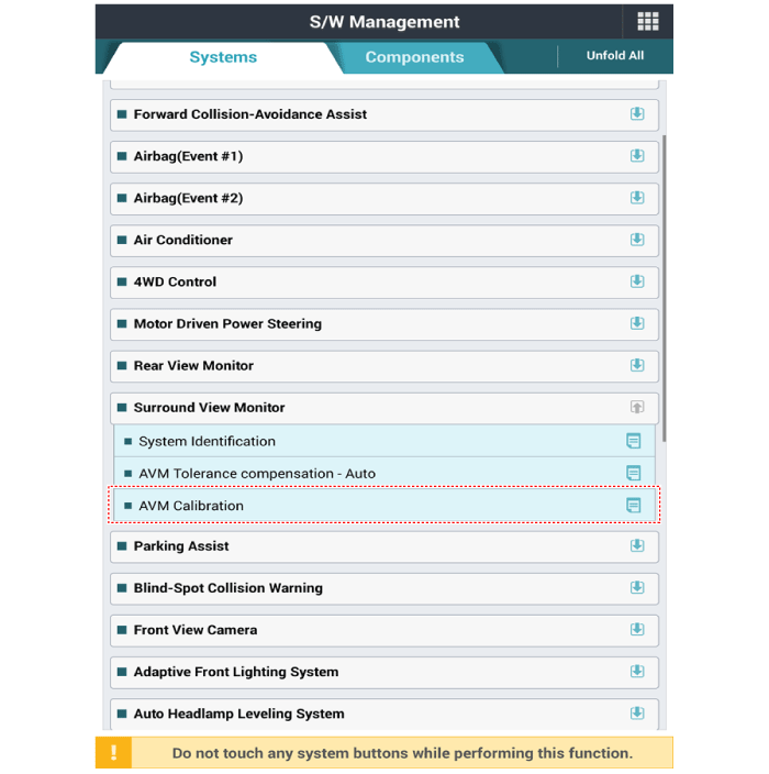
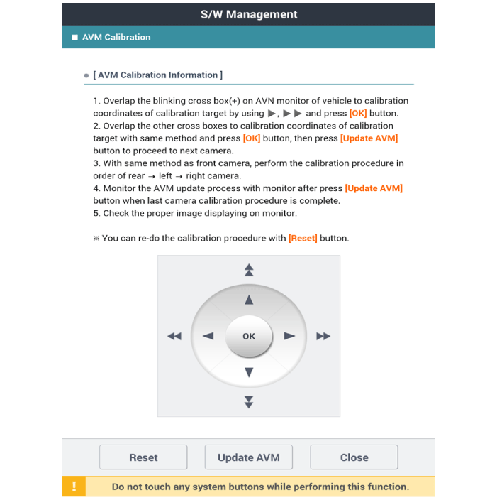
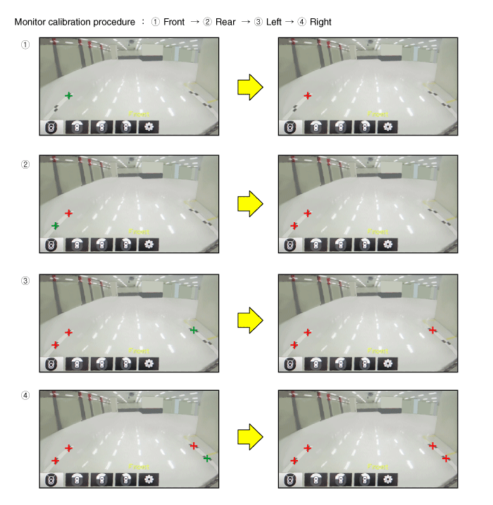
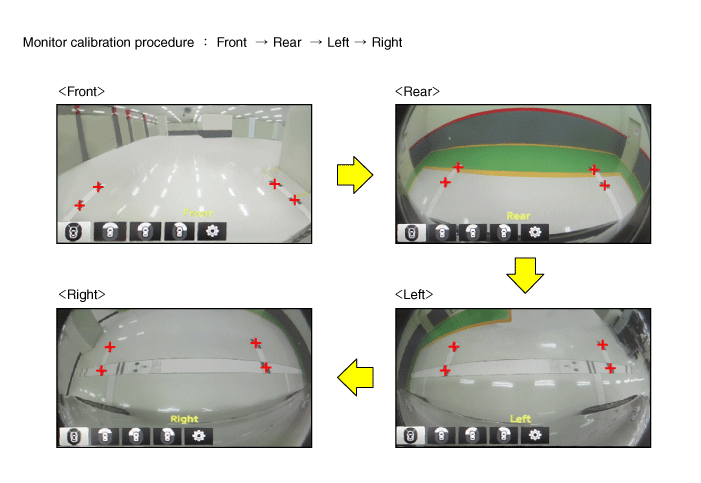
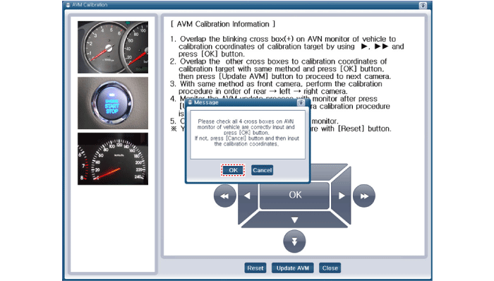
Perform SVM Calibration according to GDS diagnostics display.
|
| 7. |
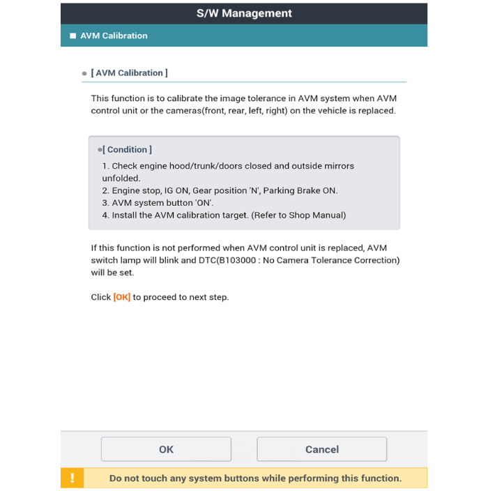
Proceed with the AVM calibration according to the GDS screen.
|
| 8. |
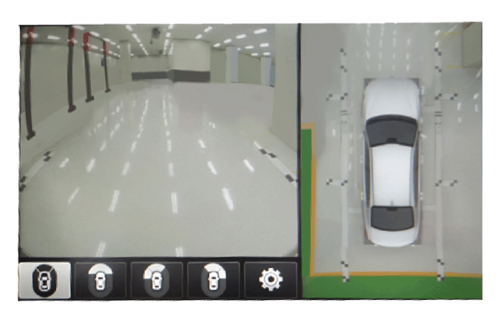
After checking the vehicle and calibration line on the AVN monitor screen
to see if the calibration has been performed properly, press the [OK]
button.
When calibration has not been performed properly, press the [Cancel]
button to match the calibration points again.
[AVN Monitor]
[GDS Screen]
|
 Troubleshooting
Troubleshooting
1)
After replacing controller, always check that the system operates
properly...
Other information:
Hyundai Santa Fe (TM) 2019-2025 Service Manual: Seat Heater (Non-Air Ventilation). Repair procedures
Inspection Driver/Passenger 1. Check for continuity and measure the resistance between terminals. No. Description No. Description 1 Heater (+) 3 NTC (-) 2 NTC (+) 4 Heater (-) Driver/Passenger Fabric(± 5%) Leather(± 5%) High 2...
Hyundai Santa Fe (TM) 2019-2025 Service Manual: Front Bumper Beam Assembly. Components and components location
..
Categories
- Manuals Home
- 4th Generation Santa Fe Owners Manual
- 4th Generation Santa Fe Service Manual
- Child-protector rear door locks
- Repair procedures
- Warning and indicator lights
- New on site
- Most important about car
Gauges and meters
Speedometer
.png)
The speedometer indicates the speed of the vehicle and is calibrated in miles per hour (MPH) and/or kilometers per hour (km/h).
Tachometer
.png)
Copyright © 2025 www.hsafe4.com


