Hyundai Santa Fe: Hydraulic System / 35R Clutch Control Solenoid Valve (35R/C_VFS). Repair procedures
| •
|
Refer to the DTC manual for the check procedure.
|
|
| •
|
Be careful not to damage the parts located under the vehicle
(floor under cover, fuel filter, fuel tank and canister) when
raising the vehicle using the lift.
(Refer to General Information - "Lift and Support Points")
|
| •
|
When the solenoid valve Diagnostic Trouble Codes (DTC) is on,
perform the following procedure to replace it.
|
| •
|
Automatic transaxle is composed of delicate components. Be careful
not to cause any damage on the component in the course of assembly
and disassembly.
|
| •
|
Maintain clean condition so that foreign substance does not
get into the automatic transaxle.
|
| •
|
Use a coated apron, latex gloves, and stainless tray to prevent
foreign substance from getting into the transaxle.
|
| •
|
Automatic transaxle fluid (ATF) can be reused. Collect it using
a clean 10-liter beaker.
|
|
|
1. |
Turn ignition switch OFF and disconnect the negative (-) battery cable.
|
|
2. |
Remove the air duct and the air cleaner assembly.
(Refer to Engine Mechanical System - "Air Cleaner")
|
|
3. |
Separate the air bleed hose (B) and then wiring bracket (A)

|
|
4. |
Remove the under cover.
(Refer to Engine Mechanical System - "Engine Room Under Cover")
|
|
5. |
Remove the drain plug (A) and reinstall the drain plug after draining
ATF totally.
|
Drain plug tightening torque :
33.3 - 43.1 N.m (3.4 - 4.4 kgf.m, 24.6 - 31.8 lb-ft)
|

|
• |
Replace the gasket before reinstalling the drain plug.
|
|
|
|
6. |
Loosen the mounting bolts (A) of the valve body cover.
|
Tightening torque :
11.8 - 13.7 N.m (1.2 - 1.4 kgf.m, 8.7 - 10.1 lb-ft)
|

|
• |
Be careful when removing the valve body cover because
the remaining ATF remains in the valve body cover.
|
|
|
• |
Replace the gasket (A) before reinstalling the valve
body cover.
|
|
• |
After the installation, start the engine and then check
if there are any leakages from the valve body cover.
|

|
|
|
7. |
Loosen the bolts and then removing the main harness (A).
|
Tightening torque :
9.8 - 11.8 N.m (1.0 - 1.2 kgf·m, 7.2 - 8.7 lb-ft)
|

|
|
8. |
Remove the support bracket (A).
|
Tightening torque :
9.8 - 11.8N.m (1.0 - 1.2 kgf.m, 7.2 - 8.7 lb-ft)
|

|
|
9. |
Remove the roller (A) and bolt (B).
|
Tightening torque :
9.8 - 11.8N.m (1.0 - 1.2 kgf.m, 7.2 - 8.7 lb-ft)
|

|
|
10. |
Remove the 35R clutch control solenoid valve (A).

|
| •
|
Note the value carefully and check the value again before assembly
|
| •
|
Inputting an invalid value (A) may cause the abnormal shifting
shock while TCM learning.

|
|
|
1. |
To install, reverse the removal procedure.
|
|
2. |
Inject the automatic transaxle oil and inspect the oil level.
(Refer to Automatic Transaxle System - "Automatic Transaxle Fluid (ATF)")
|
• |
After ATF level check or exchange, be sure to remove
residual ATF on transaxle case.
(Be especially sure to remove residual ATF between automatic
transaxle case and valve body cover)
|
|
• |
After installing the valve body cover, make sure to
check the oil leakage at the connection area with the
engine ON.
|
|
|
|
3. |
Clear the diagnostic trouble codes (DTC) using the diagnostic tool.
|
• |
Even though disconnecting the battery negative terminal,
the DTCs will not be cleared. So, be sure to clear the
DTCs using the diagnostic tool.
|
|
|
|
4. |
Reset the automatic transaxle adaptive values using the diagnostic tool.

|
|
5. |
Input the oil pressure characteristics using the diagnostic tool.
|
(1) |
Select ‘Oil-pressure Characteristics (Solenoid Valve Replacement)’
in the S/W Management.

|
|
(2) |
Select the replaced solenoid valve.

|
|
(3) |
Check the code marked on the solenoid valve.
(※ Caution : Check the code at first before replacement)

|
|
(4) |
If the code is inputted 2 times correctly, the procedure is
completed.

|
|
|
6. |
In order to prevent start delay and gear shift shock during acceleration
and start, perform TCM learning after replacing the solenoid valve.
(Refer to Automatic Transaxle Control System - "Repair Procedures")
|
Specifications
▷ Control type : Normally low type
Shape
Items
Specifications
Control current [mA]
0 - 1100
Supply pressure [kpa (kgf/cm², psi)]
1569...
Description
•
Underdrive brake control solenoid valve(UD/B) is attached to the valve
body.
•
This variable force solenoid valve directly controls the hydraulic pressure
inside the underdrive brake...
Other information:
Inspection
Front Seat
1.
Check for continuity and measure the resistance between terminals.
No.
Description
No.
Description
1
Heater (+)
3
NTC (-)
2
NTC (+)
4
Heater (-)
Driver/Passenger
Fabric(± 5%)
Leather(± 5%)
High
2...
..
Categories

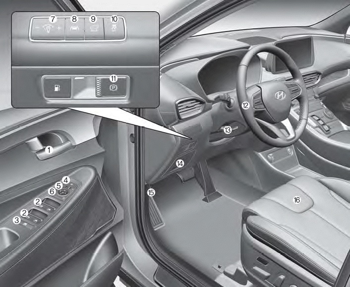
1. Inside door handle
2. Power window switches
3. Power window lock button/Electronic child safety lock button
4. Side view mirror folding button
5. Side view mirror control switch
6. Central door lock switch
7. Instrument panel illumination control switch
read more
 35R Clutch Control Solenoid Valve (35R/C_VFS). Specifications
 Underdrive Brake Control Solenoid Valve (UD/B_VFS). Description and operation


