Hyundai Santa Fe (TM): Brake System / Master Cylinder. Components and components location
| Components |
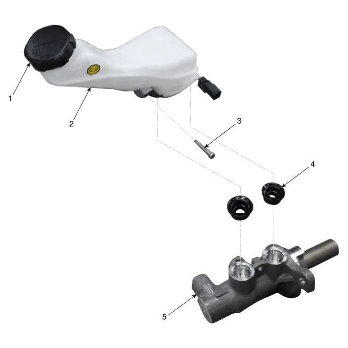
| 1. Reservoir
cap 2. Reservoir 3. Reservoir pin |
4. Grommet 5. Master cylinder |
Brake Booster Operating Test 1. Run the engine for one or two minutes, and then stop it. If the pedal depresses fully the first time but gradually becomes higher when depressed succeeding times, the booster is operating properly, if the pedal height remains unchanged, the booster is inoperative.
Removal 1. Turm ignition switch OFF and disconnect the negative (-) battery cable. 2. Remove the battery.
Other information:
Hyundai Santa Fe (TM) 2019-2023 Service and Repair Manual: Auto Defogging Sensor. Repair procedures
Inspection To inspect and diagnose the sensor, refer to Self-Diagnosis procedure and DTC guide. Replacement 1. Disconnect the negative (-) battery terminal. 2. Remove the rain sensor inner cover (A) and rain sensor cover (B).
Hyundai Santa Fe (TM) 2019-2023 Service and Repair Manual: Smart Cruise Control (SCC) Switch. Components and components location
Categories
- Manuals Home
- Hyundai Santa Fe Owners Manual
- Hyundai Santa Fe Service Manual
- Auto Hold. Warning messages
- Troubleshooting
- LCD Display
- New on site
- Most important about car
