Hyundai Santa Fe (TM): ETC (Electronic Throttle Control) System / Repair procedures
Throttle Position Sensor (TPS)
|
1. |
Connect the diagnostic tool on the Data Link Connector (DLC).
|
|
2. |
Start the engine and measure the output voltage of TPS 1 and 2 at C.T.
and W.O.T.
Throttle Angle
|
Output Voltage (V)
|
TPS 1
|
TPS 2
|
C.T
|
0.3 - 0.9
|
4.2 - 5.0
|
W.O.T
|
1.5 - 3.0
|
3.3 - 3.8
|
|
|
3. |
Turn the ignition switch OFF and disconnect the scantool from the DLC.
|
|
4. |
Disconnect the ETC module connector and measure the resistance between
the ETC module terminals 1 and 2.
|
Specification : Refer to "Specification"
|
|
ETC Motor
|
1. |
Turn the ignition switch OFF.
|
|
2. |
Disconnect the ETC module connector.
|
|
3. |
Measure resistance between the ETC module terminals 3 and 6.
|
|
4. |
Check that the resistance is within the specification.
|
Specification : Refer to "Specification"
|
|
|
1. |
Turn the ignition switch OFF and disconnect the battery negative (-)
cable.
|
|
2. |
Remove the resonator and the air intake hose.
(Refer to Engine Mechanical System - "Intake Manifold")
|
|
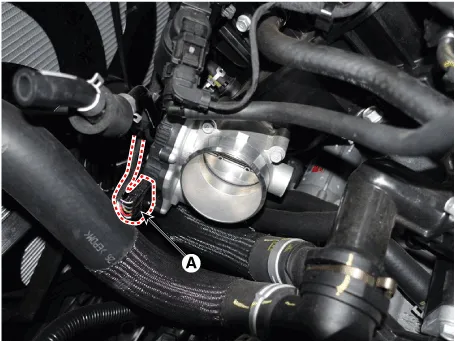
3. |
Disconnect the ETC module connector (A).
|
|
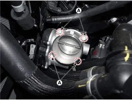
4. |
Remove the installation bolts (A), and then remove the ETC module from
the engine.
|
Tightening Torque :
7.8 - 11.8 N.m (0.8 - 1.2 kgf.m, 5.8 - 8.7 lb-ft)
|
|
| •
|
Install the component with the specified torques.
|
| •
|
Note that internal damage may occur when the component is dropped.
In this case, use it after inspecting.
|
|
|
1. |
Installation is reverse of removal.
|
Schematic Diagram
Circuit Diagram
Harness Connector
Description
Manifold Absolute Pressure Sensor (MAPS) is a speed-density type sensor and
is installed on the surge tank. It senses absolute pressure of the surge tank
and transfers the analog signal proportional to the pressure to the ECM.
Other information:
Description
Rear Corner Radar is a system that measures the relative speed and distance
from the following vehicles by using two electromagnetic wave radar sensors
attached to the rear bumper, and detects any vehicle within the blind spot zone
and gives off alarm.
Inspection
1.
Check for resistance between terminals in left switch position.
[Audio/Bluetooth]
Switch
Connector terminal
Resistance (± 3%)
SEEK Up
1 - 6
430 Ω

