Hyundai Santa Fe: Automatic Transaxle Control System / Transaxle Control Module (TCM). Description and operation
Hyundai Santa Fe (TM) 2019-2025 Service Manual / Automatic Transaxle System (SBC) / Automatic Transaxle Control System / Transaxle Control Module (TCM). Description and operation
| Description |
| • |
Monitoring the vehicle's operating conditions to determine the optimal
gear setting.
|
| • |
Performing a gear change if the current gear setting differs from the
identified optimal gear setting.
|
| • |
Determining the need for damper clutch (D/C) activation and engages
the clutch accordingly.
|
| • |
Calculating the optimal line pressure level by constantly monitoring
the torque level and adjusts the pressure accordingly.
|
| • |
Diagnosing the automatic transaxle for faults and failures.
|
 Repair procedures
Adjustment
TCM Learning
1.
Overview and purpose of learning
1)
The purpose is to ensure the initial operation safety by correcting
the oil pressure differences between transmissions...
 Transaxle Control Module (TCM). Schematic diagrams
TCM Connector and Terminal
Function
TCM Terminal Function
Connector [A]
Pin No
Description
Connected to
1
Power ground
Chassis Ground
2
-
-
3
-
-
4
-
-
5
-
-
6
Fuel Sender Signal
Fuel Sender
7
-
-
8
-
-
9
-
-
10
-
-
11
-
-
12
-
-
13
-
-
14
-
-
15
Stop Lamp Signal
Stop Lamp
16
Brake Test Switch
Brake Switch
17
18
-
19
-
20
Output Speed (Supply)
ATM Solenoid Valve (Otput Speed)
21
Input Speed (Supply)
ATM Solenoid Valve (Input Speed)
22
-
-
23
-
-
24
-
-
25
-
-
26
-
-
27
[A/T] SOL...
Other information:
Hyundai Santa Fe (TM) 2019-2025 Service Manual: Front Wheel Speed Sensor. Components and components location
..
Hyundai Santa Fe (TM) 2019-2025 Service Manual: Surround View Monitor (SVM) Camera. Repair procedures
Removal • In case of bad quality or poor focus, be sure to check the camera lense surface condition and foreign materials...
Categories
- Manuals Home
- 4th Generation Santa Fe Owners Manual
- 4th Generation Santa Fe Service Manual
- Electronic child safety lock
- Repair procedures
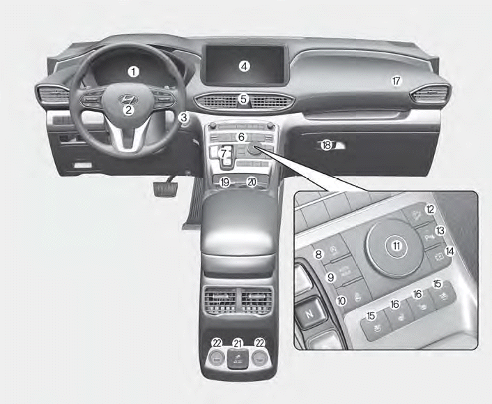
- Instrument panel overview
- New on site
- Most important about car
Instrument panel overview

1. Instrument cluster
2. Driver’s front air bag
3. Engine Start/Stop button
4. Infotainment system
5. Hazard warning lamp switch
6. Climate control system
7. Shift button
8. ISG (Idle Stop and Go) button
9. Auto Hold button
10. Heated steering wheel button
11. Drive mode button
12. DBC (Downhill Brake Control) button
13. Parking Safety button
14. Parking/View button
15. Air ventilation seat button
16. Seat warmer
17. Passenger’s front air bag
18. Glove box
19. Wireless charging system pad
20. Cup holder
21. AC inverter
22. USB charger
Copyright © 2025 www.hsafe4.com

