Hyundai Santa Fe (TM): Seat Electrical / Power Seat Control Switch. Schematic diagrams
| Circuit Diagram |
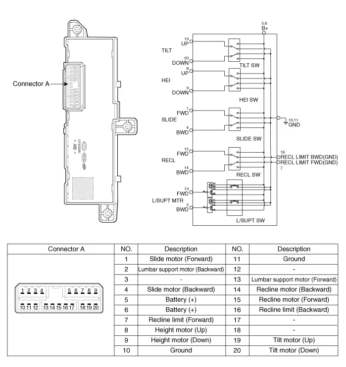
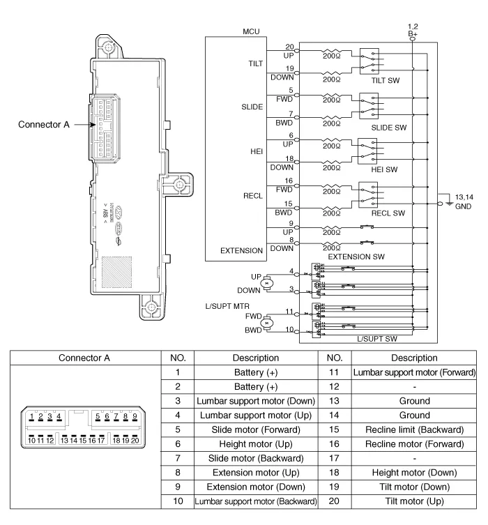
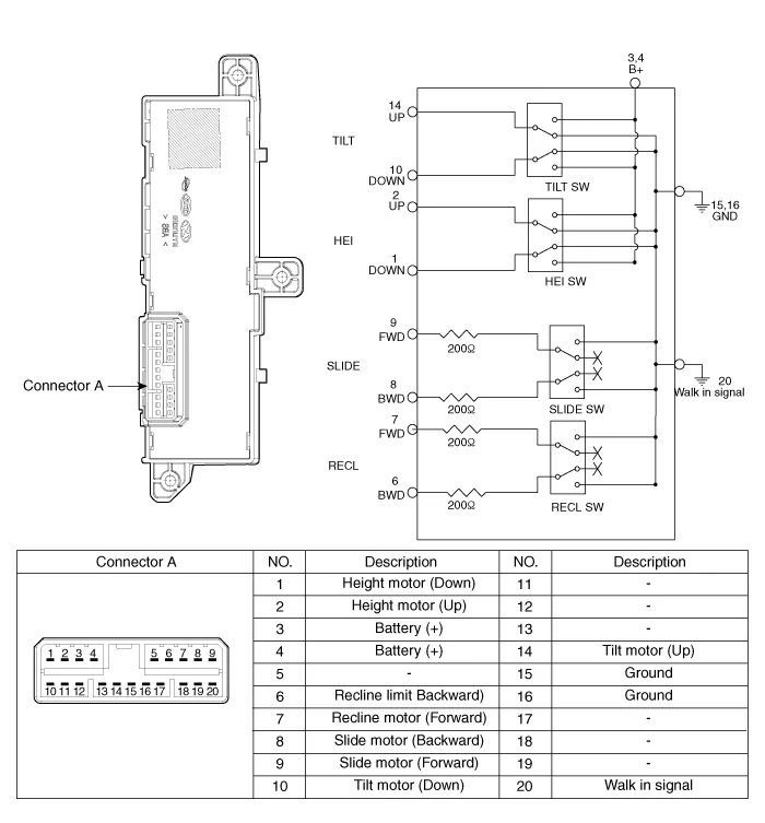
Inspection Power Seat Motor 1. Disconnect the connectors for each motor. (Refer to Body - "Front Seat Assembly") B : Rear height motor C : Front height motor D : Lumbar support motor (Horizontal) E : Lumbar supprot motor (Vertical) F : Recline motor 2.
Inspection 1. With the power seat switch in each position, make sure that continuity exists between the terminals below.
Other information:
Hyundai Santa Fe (TM) 2019-2023 Service and Repair Manual: Blower Unit. Components and components location
Components Location 1. Blower unit assembly Components 1. Blower unit assembly 2. Inlet case [LH] 3. Inlet seal 4. Inlet case [RH] 5. Intake actuator 6.
Hyundai Santa Fe (TM) 2019-2023 Service and Repair Manual: Description and operation
Description • PDW consists of 8 sensors (front : 4 units, rear : 4 units) that are used to detect obstacles and transmit the result in three separate warning levels, the first, second and third to IBU via LIN communication.
Categories
- Manuals Home
- Hyundai Santa Fe Owners Manual
- Hyundai Santa Fe Service Manual
- Heating,Ventilation And Air Conditioning
- Seats & Safety System
- Folding the side view mirror
- New on site
- Most important about car
