Hyundai Santa Fe: Airbag Module / Driver Airbag (DAB) Module and Clock Spring. Repair procedures
Hyundai Santa Fe (TM) 2019-2025 Service Manual / Restraint / Airbag Module / Driver Airbag (DAB) Module and Clock Spring. Repair procedures
| Removal |
| 1. |
Disconnect the battery negative cable and wait for at least three minutes
before beginning work.
|
| 2. |
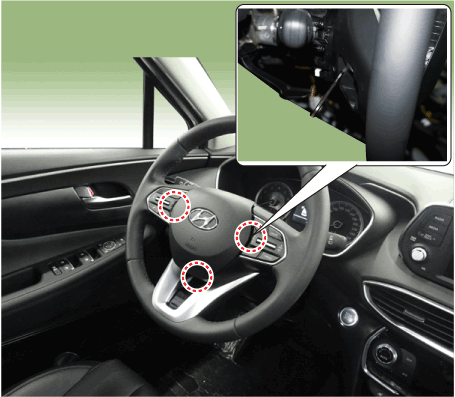
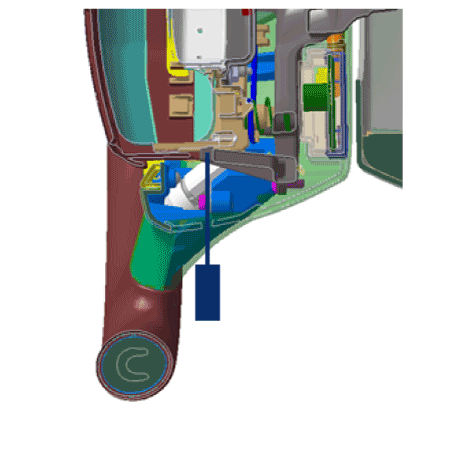
Put a flat tool (Ø5mm) into a guide hole located in the bottom of steering
wheel and press a spring.
|
| 3. |
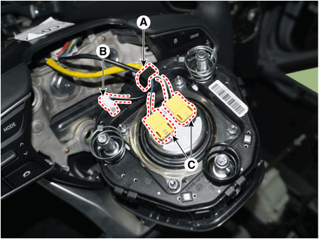
Release the connector locking (A), then disconnect the driver airbag
module connector (C) and horn connector (B).
|
| 4. |
Remove the steering wheel.
(Refer to Steering System - "Steering Column and Shaft")
|
| 5. |
Loosen the steering wheel column shroud panel.
(Refer to Body - "Steering Wheel Column Shroud Panel")
|
| 6. |
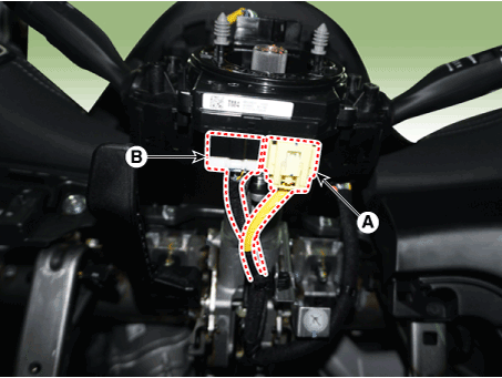
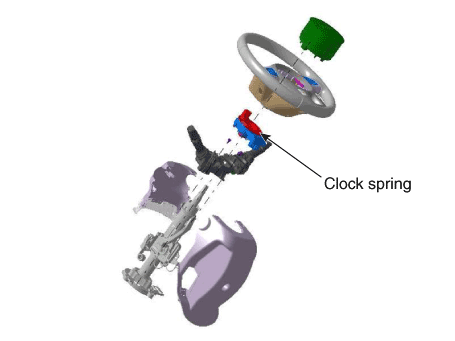
Disconnect the clock spring (A) and horn connector (B), then remove
the clock spring.
|
| Inspection |
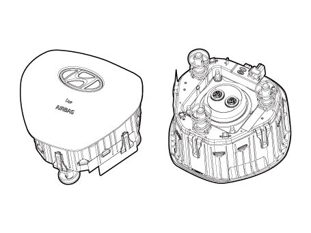
Driver Airbag (DAB)
If any improper parts are found during the following inspection, replace the
airbag module with a new one.
|
| 1. |
Check pad cover for dents, cracks or deformities.
|
| 2. |
Check the airbag module for denting, cracking or deformation.
|
| 3. |
Check hooks and connectors for damage, terminals for deformities, and
harness for binds.
|
| 4. |
Check airbag inflator case for dents, cracks or deformities.
|
Clock Spring
| 1. |
If any improper parts are found during inspection, replace the clock
spring with a new one.
|
| 2. |
Check connectors and protective tube for damage, and terminals for deformities.
|
| Installation |
| 1. |
Set the front tires straight-ahead.
|
| 2. |
Turn the ignition switch OFF.
|
| 3. |
Disconnect the battery negative cable from the battery and wait for
at least three minutes before beginning the work.
|
| 4. |
Connect the clock spring harness connector and horn harness connector
to the clock spring.
|
| 5. |
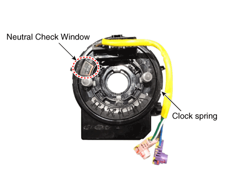
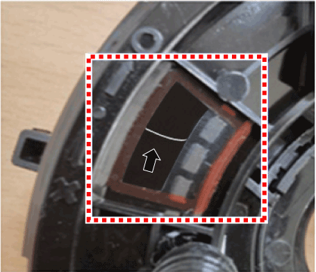
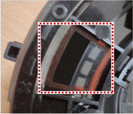
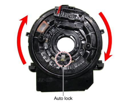
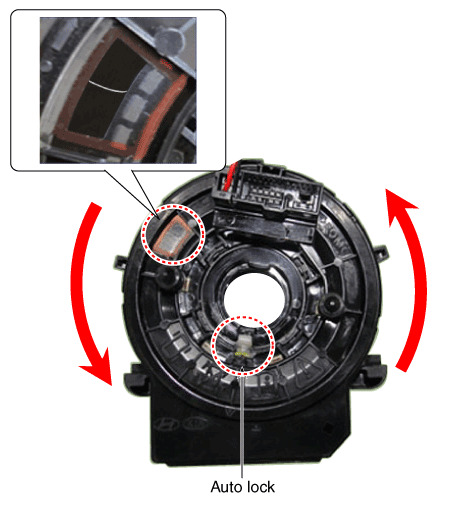
Factory setting for the clock spring is neutral.
|
| 6. |
Clock spring manual neutral setting procedure.
|
| 7. |
Install the steering wheel column shroud and the steering wheel.
(Refer to Steering System - "Steering Column and Shaft")
|
| 8. |
Connect the Driver Airbag (DAB) module connector and horn connector,
and then install the Driver Airbag (DAB) module on the steering wheel.
|
| 9. |
Connect the battery negative cable.
|
| 10. |
After installing the airbag, confirm proper system operation :
|
 Passenger Airbag (PAB) Module. Description and operation
Description
The passenger airbag (PAB) is installed inside the crash pad and protects the
front passenger in the event of a frontal crash...
Other information:
Hyundai Santa Fe (TM) 2019-2025 Owner's Manual: System settings
Setting functions for the system Lane Safety With the engine on, select ‘Driver Assistance → Lane Safety’ from the Settings menu to set whether or not to use each function. -- If ‘Assist’ is selected, the system will automatically assist the driver’s steering when lane departure is detected to help prevent the vehicle from moving out of its lane...
Hyundai Santa Fe (TM) 2019-2025 Service Manual: Transaxle Control Module (TCM). Description and operation
Description • Monitoring the vehicle's operating conditions to determine the optimal gear setting. • Performing a gear change if the current gear setting differs from the identified optimal gear setting...
Categories
- Manuals Home
- 4th Generation Santa Fe Owners Manual
- 4th Generation Santa Fe Service Manual
- Immobilizer system
- Folding the side view mirror
- Resetting the power liftgate
- New on site
- Most important about car
Gauges and meters
Speedometer
.png)
The speedometer indicates the speed of the vehicle and is calibrated in miles per hour (MPH) and/or kilometers per hour (km/h).
Tachometer
.png)
Copyright © 2025 www.hsafe4.com

